Home

TACP MG Interactive Cabling Guide

A step-by-step visual guide for system setup and verification.

⚠️Safety Precautions

  • Power Off:Ensure ALL power switches are OFF and the system is unplugged before connecting any cables.
  • Discharge Time:Allow 2 minutes for capacitors to discharge after unplugging before handling components.
  • Grounding:Always connect ground terminals to external grounds BEFORE applying power.
  • Remove Jewelry:Remove all metallic jewelry (rings, watches, etc.).
  • Cable Inspection:Inspect all cables for damage. Do NOT use damaged cables.
A. STT (Small Tactical Terminal) Connections
1
STT J8 (Antenna A) to Link 16 Antenna

Connect the STT J8 RF cable (4-notch end) to the STT J8 receptacle. Then, connect the SMA end (using a Type N to SMA adapter) to the antenna extension cable for the Link 16 Antenna.

This connector is spring-loaded. Align keys, push, and turn clockwise until it clicks.
2
STT J9 (Antenna B) to Terminator

Connect the STT J9 RF cable (3-notch end) to the STT J9 receptacle. Then, connect the 50-Watt Terminator (using a Type N to SMA adapter) to the loose end of the J9 cable.

3
UHF/VHF RF Cable (STT J7)

Connect one BNC end of the UHF/VHF RF Cable to the STT J7 receptacle. Leave the other end loose for now.

4
STT Power Input Cable (STT J5)

Connect the STT J5 end of the Power Input Cable to the STT J5 receptacle. Tighten until the red ring is not visible.

5
STT CH1 Red Control Cable (STT J1)

Connect the large singular end of the CH1 Red Control Cable to the STT J1 receptacle. Tighten until the red ring is not visible.

6
STT CH2 Audio/Fill Cable (STT J10)

Connect the male end of the CH2 Audio/Fill Cable to the STT J10 receptacle. Tighten until the red ring is not visible.

7
STT Black IO Cable (STT J3)

Connect the large singular end of the Black IO Cable to the STT J3 receptacle. Tighten until the red ring is not visible.

8
STT CH1 Audio/Fill Cable (STT J4)

Connect the male end of the CH1 Audio/Fill Cable to the STT J4 receptacle. Tighten until the red ring is not visible.

For M-Code Crypto Fill, this cable moves from STT J4 to the GIZMO FILL interface.
💻B. STT Module Connections
1
Power Input Cable: Route the cable from STT J5 and connect to the STT Module STT POWER receptacle.
2
CH1 Red Control Cable: Route the cable from STT J1. Connect the RED end to CH1 CONTROL and the ETH end to CH1 CONTROL ETH 2.
3
CH2 Red Control Cable: Route the cable from STT J2. Connect the RED end to CH2 CONTROL and the ETH end to CH2 CONTROL ETH 2.
4
Black IO Cable: Connect the small female end of the cable from STT J3 to the STT Module Black IO receptacle.
5
EXP/External Power Cable: Connect the singular female end to the STT Module EXP POWER receptacle.
6
Remote KDU: Connect the KDU cable to the desired CH1/CH2 KDU CONTROL receptacle.
🖥️C. PacStar 453/447 Connections
1
Router to STT Module CH1

Connect PacStar 447 Router to CH1 CONTROL ETH 1

PacStar 447 GI1/1 STT Module CH1 ETH 1
2
Router to STT Module CH2

Connect PacStar 447 Router to CH2 CONTROL ETH 1

PacStar 447 GI1/2 STT Module CH2 ETH 1
3
Server to Router Link

Connect PacStar 447 Router to PacStar 453 Server

PacStar 453 ETH0 PacStar 447 GI1/0
4
Router to GIZMO

Connect PacStar 447 Router to GIZMO

PacStar 447 GI1/3 GIZMO ETH
5
USB Hub & Display

Connect the USB Hub to a PacStar 453 USB 3.1 port. Connect an external monitor to a PacStar 453 Display Port/HDMI output.

📡D. GIZMO (GPS) Connections
1
GIZMO Power: From the STT Module EXP Power cable, connect the "GIZMO Power" end to the GIZMO PWR IN receptacle.
2
GIZMO Antenna: Connect the 50 ft. RG58 cable from the GIZMO ANT receptacle to the GPS Antenna. Place antenna with a clear view of the sky.
3
GIZMO Data (Choose ONE):
  • Preferred: Connect GIZMO INT 1/2 cable (INT 2 USB end) to the PacStar 453 USB/Hub.
  • Alternative: Connect GIZMO INT 3 cable (USB end) to the PacStar 453 USB/Hub.
Do NOT connect both data cables simultaneously.
4
GIZMO PPS for ETR (Optional): For ETR, connect the GIZMO 24 in. cable from GIZMO PPS 3 to the loose BNC on the STT J3 Black IO cable.
E. Ultralife Amplifier
1
Ultralife Power: From the STT Module EXP Power cable, connect the "RF AMP PWR" end from the EXP Power cable to the amplifier's PWR receptacle.
2
R/T Receptacle: Connect the loose BNC from STT J7 to the amplifier's ANT R/T receptacle.
3
RF Antenna Cable: Connect the LOS Antenna cable to the amplifier's ANT receptacle.
F. Additional Connections
1
RDP Computer: Connect an Ethernet cable (length depending on situation) to the PacStar 453 Server ETH1.
Connect the other end of the Ethernet cable to a computer to run RDP.
    RDP Interface Configuration:
  • IP: 192.168.69.17
  • Subnet Mask: 255.255.255.0
  • Gateway: 192.168.69.117
2
AN/PRC-163 Radio: Connect the user-provided Harris USB data cable from the radio's side shoe interface to an open port on the USB Hub.
3
STT USB adapterConnect STT USB adapter (VPN 1411843) to corresponding connector on STT CH2 Red Control cable.
Use Cases:
  • VMF
  • STT Software or Mission Plan install
Can also be used on STT CH1 Red Control
🔌G. Main System Power
1
Verify Power Off: Ensure the PacStar chassis power switch is OFF (toggled right, green light off).
2
Connect Power to PacStar Case:
AC Power: Connect the 3-prong female AC power cable to the VAC INPUT male connector in the rear of the PacStar case.
If using VDC power, connect the PacStar 4-pin female power cable connector to the 4-pin male VAC INPUT connector.
3
Connect Power to STT Power Module:
AC Power: Connect the 3-pin female AC power cable to the VAC IN male connector in the rear of the STT Power Module.
If using VDC power, connect the STT power module 4-pin female cable connector to the 4-pin male VAC IN connector.
4
Connect PacStar and STT to Power Source: Connect the main power cable to a reliable AC or DC power source / power strip.
🖼️Cabling Diagrams

Click on an image to enlarge.

Cabling Diagram

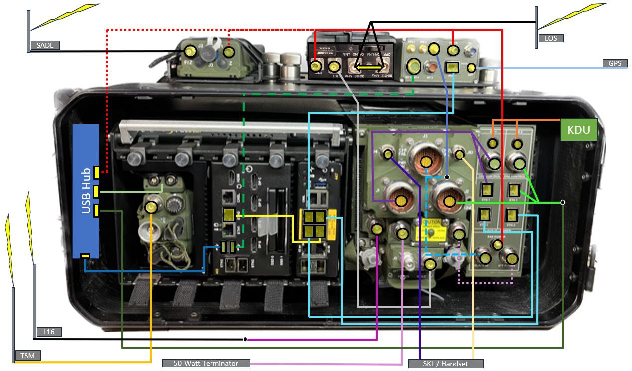
Main Cabling Diagram
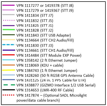
Cabling Diagram Legend

Diagram Legend